Kubernetes Validate GPU Accelerator Access Isolation in OKE

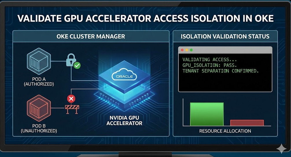
In multi-tenant high-performance computing (HPC) environments, ensuring strict resource boundaries is not just a performance concern—it is a critical security requirement. For Oracle Cloud Infrastructure Container Engine for Kubernetes (OKE), verifying GPU Accelerator Access Isolation is paramount when running untrusted workloads alongside critical AI/ML inference tasks. This guide targets expert Platform Engineers and SREs, focusing on the mechanisms, configuration, and practical validation of GPU isolation within OKE clusters.

The Mechanics of GPU Isolation in Kubernetes

Before diving into validation, it is essential to understand how OKE and the underlying container runtime mediate access to hardware accelerators. Unlike CPU and RAM, which are compressible resources managed via cgroups, GPUs are treated as extended resources.

Pro-Tip: The default behavior of the NVIDIA Container Runtime is often permissive. Without the NVIDIA Device Plugin explicitly setting environment variables like NVIDIA_VISIBLE_DEVICES, a container might gain access to all GPU devices on the node. Isolation relies heavily on the correct interaction between the Kubelet, the Device Plugin, and the Container Runtime Interface (CRI).

Isolation Layers

  • Physical Isolation (Passthrough): Giving a Pod exclusive access to a specific PCle device.
  • Logical Isolation (MIG): Using Multi-Instance GPU (MIG) on Ampere architectures (e.g., A100) to partition a single physical GPU into multiple isolated instances with dedicated compute, memory, and cache.
  • Time-Slicing: Sharing a single GPU context across multiple processes (weakest isolation, mostly for efficiency, not security).

Prerequisites for OKE

To follow this validation procedure, ensure your environment meets the following criteria:

  • An active OKE Cluster (version 1.25+ recommended).
  • Node pools using GPU-enabled shapes (e.g., VM.GPU.A10.1, BM.GPU.A100-vCP.8).
  • The NVIDIA Device Plugin installed (standard in OKE GPU images, but verify the daemonset).
  • kubectl context configured for administrative access.

Step 1: Establishing the Baseline (The “Rogue” Pod)

To validate GPU Accelerator Access Isolation, we must first attempt to access resources from a Pod that has not requested them. This simulates a “rogue” workload attempting to bypass resource quotas or scrape data from GPU memory.

Deploying a Non-GPU Workload

Deploy a standard pod that includes the NVIDIA utilities but requests 0 GPU resources.

apiVersion: v1
kind: Pod
metadata:
  name: gpu-rogue-validation
  namespace: default
spec:
  restartPolicy: Never
  containers:
  - name: cuda-container
    image: nvcr.io/nvidia/k8s/cuda-sample:nbody-cuda11.7.1-ubuntu20.04
    command: ["sleep", "3600"]
    # CRITICAL: No resources.limits.nvidia.com/gpu defined here
    resources:
      limits:
        cpu: "500m"
        memory: "512Mi"

Verification Command

Exec into the pod and attempt to query the GPU status. If isolation is working correctly, the NVIDIA driver should report no devices found or the command should fail.

kubectl exec -it gpu-rogue-validation -- nvidia-smi

Expected Outcome:

  • Failed to initialize NVML: Unknown Error
  • Or, a clear output stating No devices were found.

If this pod returns a full list of GPUs, isolation has failed. This usually indicates that the default runtime is exposing all devices because the Device Plugin did not inject the masking environment variables.

Step 2: Validating Authorized Access

Now, deploy a valid workload that requests a specific number of GPUs to ensure the scheduler and device plugin are correctly allocating resources.

apiVersion: v1
kind: Pod
metadata:
  name: gpu-authorized
spec:
  restartPolicy: Never
  containers:
  - name: cuda-container
    image: nvcr.io/nvidia/k8s/cuda-sample:nbody-cuda11.7.1-ubuntu20.04
    command: ["sleep", "3600"]
    resources:
      limits:
        nvidia.com/gpu: 1 # Requesting 1 GPU

Inspection

Run nvidia-smi inside this pod. You should see exactly one GPU device.

Furthermore, inspect the environment variables injected by the plugin:

kubectl exec gpu-authorized -- env | grep NVIDIA_VISIBLE_DEVICES

This should return a UUID (e.g., GPU-xxxxxxxx-xxxx-xxxx...) rather than all.

Step 3: Advanced Validation with MIG (Multi-Instance GPU)

For workloads requiring strict hardware-level isolation on OKE using A100 instances, you must validate MIG partitioning. GPU Accelerator Access Isolation in a MIG context means a Pod on “Instance A” cannot impact the memory bandwidth or compute units of “Instance B”.

If you have configured MIG strategies (e.g., mixed or single) in your OKE node pool:

  1. Deploy two separate pods, each requesting nvidia.com/mig-1g.5gb (or your specific profile).
  2. Run a stress test on Pod A:
    kubectl exec -it pod-a -- /usr/local/cuda/samples/1_Utilities/deviceQuery/deviceQuery

  3. Verify UUIDs: Ensure the UUID visible in Pod A is distinct from Pod B.
  4. Crosstalk Check: Attempt to target the GPU index of Pod B from Pod A using CUDA code. It should fail with an invalid device error.

Troubleshooting Isolation Leaks

If your validation tests fail (i.e., the “rogue” pod can see GPUs), check the following configurations in your OKE cluster.

1. Privileged Security Context

A common misconfiguration is running containers as privileged. This bypasses the container runtime’s device cgroup restrictions.

# AVOID THIS IN MULTI-TENANT CLUSTERS
securityContext:
  privileged: true

Fix: Enforce Pod Security Standards (PSS) to disallow privileged containers in non-system namespaces.

2. HostPath Volume Mounts

Ensure users are not mounting /dev or /var/run/nvidia-container-devices directly. Use OPA Gatekeeper or Kyverno to block HostPath mounts that expose device nodes.

Frequently Asked Questions (FAQ)

Does OKE enable GPU isolation by default?

Yes, OKE uses the standard Kubernetes Device Plugin model. However, “default” relies on the assumption that you are not running privileged containers. You must actively validate that your RBAC and Pod Security Policies prevent privilege escalation.

Can I share a single GPU across two Pods safely?

Yes, via Time-Slicing or MIG. However, Time-Slicing does not provide memory isolation (OOM in one pod can crash the GPU context for others). For true isolation, you must use MIG (available on A100 shapes in OKE).

How do I monitor GPU violations?

Standard monitoring (Prometheus/Grafana) tracks utilization, not access violations. To detect access violations, you need runtime security tools like Falco, configured to alert on unauthorized open() syscalls on /dev/nvidia* devices by pods that haven’t requested them.

Conclusion

Validating GPU Accelerator Access Isolation in OKE is a non-negotiable step for securing high-value AI infrastructure. By systematically deploying rogue and authorized pods, inspecting environment variable injection, and enforcing strict Pod Security Standards, you verify that your multi-tenant boundaries are intact. Whether you are using simple passthrough or complex MIG partitions, trust nothing until you have seen the nvidia-smi output deny access. Thank you for reading the DevopsRoles page!

Optimize Kubernetes Request Right Sizing with Kubecost for Cost Savings

In the era of cloud-native infrastructure, the scheduler is king. However, the efficiency of that scheduler depends entirely on the accuracy of the data you feed it. For expert Platform Engineers and SREs, Kubernetes request right sizing is not merely a housekeeping task—it is a critical financial and operational lever. Over-provisioning leads to “slack” (billed but unused capacity), while under-provisioning invites CPU throttling and OOMKilled events.

This guide moves beyond the basics of resources.yaml. We will explore the mechanics of resource contention, the algorithmic approach Kubecost takes to optimization, and how to implement a data-driven right-sizing strategy that balances cost reduction with production stability.

The Technical Economics of Resource Allocation

To master Kubernetes request right sizing, one must first understand how the Kubernetes scheduler and the underlying Linux kernel interpret these values.

The Scheduler vs. The Kernel

Requests are primarily for the Kubernetes Scheduler. They ensure a node has enough allocatable capacity to host a Pod. Limits, conversely, are enforced by the Linux kernel via cgroups.

  • CPU Requests: Determine the cpu.shares in cgroups. This is a relative weight, ensuring that under contention, the container gets its guaranteed slice of time.
  • CPU Limits: Determine cpu.cfs_quota_us. Hard throttling occurs immediately if this quota is exceeded within a period (typically 100ms), regardless of node idleness.
  • Memory Requests: Primarily used for scheduling.
  • Memory Limits: Enforce the OOM Killer threshold.

Pro-Tip (Expert): Be cautious with CPU limits. While they prevent a runaway process from starving neighbors, they can introduce tail latency due to CFS throttling bugs or micro-bursts. Many high-performance shops (e.g., at the scale of Twitter or Zalando) choose to set CPU Requests but omit CPU Limits for Burstable workloads, relying on cpu.shares for fairness.

Why “Guesstimation” Fails at Scale

Manual right-sizing is impossible in dynamic environments. Developers often default to “safe” (bloated) numbers, or copy-paste manifests from StackOverflow. This results in the “Kubernetes Resource Gap”: the delta between Allocated resources (what you pay for) and Utilized resources (what you actually use).

Without tooling like Kubecost, you are likely relying on static Prometheus queries that look like this to find usage peaks:

max_over_time(container_memory_working_set_bytes{namespace="production"}[24h])

While useful, raw PromQL queries lack context regarding billing models, spot instance savings, and historical seasonality. This is where Kubernetes request right sizing via Kubecost becomes essential.

Implementing Kubecost for Granular Visibility

Kubecost models your cluster’s costs by correlating real-time resource usage with your cloud provider’s billing API (AWS Cost Explorer, GCP Billing, Azure Cost Management).

1. Installation & Prometheus Integration

For production clusters, installing via Helm is standard. Ensure you are scraping metrics at a resolution high enough to catch micro-bursts, but low enough to manage TSDB cardinality.

helm repo add kubecost https://kubecost.github.io/cost-analyzer/
helm upgrade --install kubecost kubecost/cost-analyzer \
    --namespace kubecost --create-namespace \
    --set kubecostToken="YOUR_TOKEN_HERE" \
    --set prometheus.server.persistentVolume.enabled=true \
    --set prometheus.server.retention=15d

2. The Right-Sizing Algorithm

Kubecost’s recommendation engine doesn’t just look at “now.” It analyzes a configurable window (e.g., 2 days, 7 days, 30 days) to recommend Kubernetes request right sizing targets.

The core logic typically follows a usage profile:

  • Peak Aware: It identifies max(usage) over the window to prevent OOMs.
  • Headroom Buffer: It adds a configurable overhead (e.g., 15-20%) to the recommendation to account for future growth or sudden spikes.

Executing the Optimization Loop

Once Kubecost is ingesting data, navigate to the Savings > Request Right Sizing dashboard. Here is the workflow for an SRE applying these changes.

Step 1: Filter by Namespace and Owner

Do not try to resize the entire cluster at once. Filter by namespace: backend or label: team=data-science.

Step 2: Analyze the “Efficiency” Score

Kubecost assigns an efficiency score based on the ratio of idle to used resources.

Target: A healthy range is typically 60-80% utilization. Approaching 100% is dangerous; staying below 30% is wasteful.

Step 3: Apply the Recommendation (GitOps)

As an expert, you should never manually patch a deployment via `kubectl edit`. Take the recommended YAML values from Kubecost and update your Helm Charts or Kustomize bases.

# Before Optimization
resources:
  requests:
    memory: "4Gi" # 90% idle based on Kubecost data
    cpu: "2000m"

# After Optimization (Kubecost Recommendation)
resources:
  requests:
    memory: "600Mi" # calculated max usage + 20% buffer
    cpu: "350m"

Advanced Strategy: Automating with VPA

Static right-sizing has a shelf life. As traffic patterns change, your static values become obsolete. The ultimate maturity level in Kubernetes request right sizing is coupling Kubecost’s insights with the Vertical Pod Autoscaler (VPA).

Kubecost can integrate with VPA to automatically apply recommendations. However, in production, “Auto” mode is risky because it restarts Pods to change resource specifications.

Warning: For critical stateful workloads (like Databases or Kafka), use VPA in Off or Initial mode. This allows VPA to calculate the recommendation object, which you can then monitor via metrics or export to your GitOps repo, without forcing restarts.

VPA Configuration for Recommendations Only

apiVersion: autoscaling.k8s.io/v1
kind: VerticalPodAutoscaler
metadata:
  name: backend-service-vpa
spec:
  targetRef:
    apiVersion: "apps/v1"
    kind: Deployment
    name: backend-service
  updatePolicy:
    updateMode: "Off" # Kubecost reads the recommendation; VPA does not restart pods.

Frequently Asked Questions (FAQ)

1. How does right-sizing affect Quality of Service (QoS) classes?

Right-sizing directly dictates QoS.

Guaranteed: Requests == Limits. Safest, but most expensive.

Burstable: Requests < Limits. Ideal for most HTTP web services.

BestEffort: No requests/limits. High risk of eviction.

When you lower requests to save money, ensure you don’t accidentally drop a critical service from Guaranteed to Burstable if strict isolation is required.

2. Can I use Kubecost to resize specific sidecars (like Istio/Envoy)?

Yes. Sidecars often suffer from massive over-provisioning because they are injected with generic defaults. Kubecost breaks down usage by container, allowing you to tune the istio-proxy container independently of the main application container.

3. What if my workload has very “spiky” traffic?

Standard averaging algorithms fail with spiky workloads. In Kubecost, adjust the profiling window to a shorter duration (e.g., 2 days) to capture recent spikes, or ensure your “Target Utilization” threshold is set lower (e.g., 50% instead of 80%) to leave a larger safety buffer for bursts.

Conclusion

Kubernetes request right sizing is not a one-time project; it is a continuous loop of observability and adjustment. By leveraging Kubecost, you move from intuition-based guessing to data-driven precision.

The goal is not just to lower the cloud bill. The goal is to maximize the utility of every CPU cycle you pay for while guaranteeing the stability your users expect. Start by identifying your top 10 most wasteful deployments, apply the “Requests + Buffer” logic, and integrate these checks into your CI/CD pipelines to prevent resource drift before it hits production. Thank you for reading the DevopsRoles page!

AWS SDK for Rust: Your Essential Guide to Quick Setup

In the evolving landscape of cloud-native development, the AWS SDK for Rust represents a paradigm shift toward memory safety, high performance, and predictable resource consumption. While languages like Python and Node.js have long dominated the AWS ecosystem, Rust provides an unparalleled advantage for high-throughput services and cost-optimized Lambda functions. This guide moves beyond the basics, offering a technical deep-dive into setting up a production-ready environment using the SDK.

Pro-Tip: The AWS SDK for Rust is built on top of smithy-rs, a code generator capable of generating SDKs from Smithy models. This architecture ensures that the Rust SDK stays in sync with AWS service updates almost instantly.

1. Project Initialization and Dependency Management

To begin working with the AWS SDK for Rust, you must configure your Cargo.toml carefully. Unlike monolithic SDKs, the Rust SDK is modular. You only include the crates for the services you actually use, which significantly reduces compile times and binary sizes.

Every project requires the aws-config crate for authentication and the specific service crates (e.g., aws-sdk-s3). Since the SDK is inherently asynchronous, a runtime like Tokio is mandatory.

[dependencies]
# Core configuration and credential provider
aws-config = { version = "1.1", features = ["behavior-version-latest"] }

# Service specific crates
aws-sdk-s3 = "1.17"
aws-sdk-dynamodb = "1.16"

# Async runtime
tokio = { version = "1", features = ["full"] }

# Error handling
anyhow = "1.0"

2. Deep Dive: Configuring the AWS SDK for Rust

The entry point for almost any application is the aws_config::load_from_env() function. For expert developers, understanding how the SdkConfig object manages the credential provider chain and region resolution is critical for debugging cross-account or cross-region deployments.

Asynchronous Initialization

The SDK uses async/await throughout. Here is the standard boilerplate for a robust initialization:

use aws_config::meta::region::RegionProviderChain;
use aws_config::BehaviorVersion;

#[tokio::main]
async fn main() -> Result<(), anyhow::Error> {
    // Determine region, falling back to us-east-1 if not set
    let region_provider = RegionProviderChain::default_provider().or_else("us-east-1");
    
    // Load configuration with the latest behavior version for future-proofing
    let config = aws_config::defaults(BehaviorVersion::latest())
        .region(region_provider)
        .load()
        .await;

    // Initialize service clients
    let s3_client = aws_sdk_s3::Client::new(&config);
    
    println!("AWS SDK for Rust initialized for region: {:?}", config.region().unwrap());
    Ok(())
}

Advanced Concept: The BehaviorVersion parameter is crucial. It allows the AWS team to introduce breaking changes to default behaviors (like retry logic) without breaking existing binaries. Always use latest() for new projects or a specific version for legacy stability.

3. Production Patterns: Interacting with Services

Once the AWS SDK for Rust is configured, interacting with services follows a consistent “Builder” pattern. This pattern ensures type safety and prevents the construction of invalid requests at compile time.

Example: High-Performance S3 Object Retrieval

When fetching large objects, leveraging Rust’s stream handling is significantly more efficient than buffering the entire payload into memory.

use aws_sdk_s3::Client;

async fn download_object(client: &Client, bucket: &str, key: &str) -> Result<(), anyhow::Error> {
    let resp = client
        .get_object()
        .bucket(bucket)
        .key(key)
        .send()
        .await?;

    let data = resp.body.collect().await?;
    println!("Downloaded {} bytes", data.into_bytes().len());

    Ok(())
}

4. Error Handling and Troubleshooting

Error handling in the AWS SDK for Rust is exhaustive. Each operation returns a specialized error type that distinguishes between service-specific errors (e.g., NoSuchKey) and transient network failures.

  • Service Errors: Errors returned by the AWS API (4xx or 5xx).
  • SdkErrors: Errors related to the local environment, such as construction failures or timeouts.

For more details on error structures, refer to the Official Smithy Error Documentation.

FeatureRust AdvantageImpact on DevOps
Memory SafetyZero-cost abstractions/OwnershipLower crash rates in production.
Binary SizeModular cratesFaster Lambda cold starts.
ConcurrencyFearless concurrency with TokioHigh throughput on minimal hardware.

Frequently Asked Questions (FAQ)

Is the AWS SDK for Rust production-ready?

Yes. As of late 2023, the AWS SDK for Rust is General Availability (GA). It is used internally by AWS and by numerous high-scale organizations for production workloads.

How do I handle authentication for local development?

The SDK follows the standard AWS credential provider chain. It will automatically check for environment variables (AWS_ACCESS_KEY_ID), the ~/.aws/credentials file, and IAM roles if running on EC2 or EKS.

Can I use the SDK without Tokio?

While the SDK is built to be executor-agnostic in theory, currently, aws-config and the default HTTP clients are heavily integrated with Tokio and Hyper. Using a different runtime requires implementing custom HTTP connectors.

Conclusion

Setting up the AWS SDK for Rust is a strategic move for developers who prioritize performance and reliability. By utilizing the modular crate system, embracing the async-first architecture of Tokio, and understanding the SdkConfig lifecycle, you can build cloud applications that are both cost-effective and remarkably fast. Whether you are building microservices on EKS or high-performance Lambda functions, Rust offers the tooling necessary to master the AWS ecosystem.

Would you like me to generate a specialized guide on optimizing AWS Lambda cold starts using the Rust SDK and Cargo Lambda? Thank you for reading the DevopsRoles page!

Mastering AWS Account Deployment: Terraform & AWS Control Tower

For modern enterprises, AWS account deployment is no longer a manual task of clicking through the AWS Organizations console. As infrastructure scales, the need for consistent, compliant, and automated “vending machines” for AWS accounts becomes paramount. By combining the governance power of AWS Control Tower with the Infrastructure as Code (IaC) flexibility of Terraform, SREs and Cloud Architects can build a robust deployment pipeline that satisfies both developer velocity and security requirements.

The Foundations: Why Control Tower & Terraform?

In a decentralized cloud environment, AWS account deployment must address three critical pillars: Governance, Security, and Scalability. While AWS Control Tower provides the managed “Landing Zone” environment, Terraform provides the declarative state management required to manage thousands of resources across multiple accounts without configuration drift.

Advanced Concept: Control Tower uses “Guardrails” (Service Control Policies and Config Rules). When deploying accounts via Terraform, you aren’t just creating a container; you are attaching a policy-driven ecosystem that inherits the root organization’s security posture by default.

By leveraging the Terraform AWS Provider alongside Control Tower, you enable a “GitOps” workflow where an account request is simply a .tf file in a repository. This approach ensures that every account is born with the correct IAM roles, VPC configurations, and logging buckets pre-provisioned.

Deep Dive: Account Factory for Terraform (AFT)

The AWS Control Tower Account Factory for Terraform (AFT) is the official bridge between these two worlds. AFT sets up a separate orchestration engine that listens for Terraform changes and triggers the Control Tower account creation API.

The AFT Component Stack

  • AFT Management Account: A dedicated account within your Organization to host the AFT pipeline.
  • Request Metadata: A DynamoDB table or Git repo that stores account parameters (Email, OU, SSO user).
  • Customization Pipeline: A series of Step Functions and Lambda functions that apply “Global” and “Account-level” Terraform modules after the account is provisioned.

Step-by-Step: Deploying Your First Managed Account

To master AWS account deployment via AFT, you must understand the structure of an account request. Below is a production-grade example of a Terraform module call to request a new “Production” account.


module "sandbox_account" {
  source = "github.com/aws-ia/terraform-aws-control_tower_account_factory"

  control_tower_parameters = {
    AccountEmail              = "cloud-ops+prod-app-01@example.com"
    AccountName               = "production-app-01"
    ManagedOrganizationalUnit = "Production"
    SSOUserEmail              = "admin@example.com"
    SSOUserFirstName          = "Platform"
    SSOUserLastName           = "Team"
  }

  account_tags = {
    "Project"     = "Apollo"
    "Environment" = "Production"
    "CostCenter"  = "12345"
  }

  change_management_parameters = {
    change_requested_by = "DevOps Team"
    change_reason       = "New microservice deployment for Q4"
  }

  custom_fields = {
    vpc_cidr = "10.0.0.0/20"
  }
}

After applying this Terraform code, AFT triggers a workflow in the background. It calls the Control Tower ProvisionProduct API, waits for the account to be “Ready,” and then executes your post-provisioning Terraform modules to set up VPCs, IAM roles, and CloudWatch alarms.

Production-Ready Best Practices

Expert SREs know that AWS account deployment is only 20% of the battle; the other 80% is maintaining those accounts. Follow these standards:

  • Idempotency is King: Ensure your post-provisioning scripts can run multiple times without failure. Use Terraform’s lifecycle { prevent_destroy = true } on critical resources like S3 logging buckets.
  • Service Quota Management: Newly deployed accounts start with default limits. Use the aws_servicequotas_service_quota resource to automatically request increases for EC2 instances or VPCs during the deployment phase.
  • Region Deny Policies: Use Control Tower guardrails to restrict deployments to approved regions. This reduces your attack surface and prevents “shadow IT” in unmonitored regions like me-south-1.
  • Centralized Logging: Always ensure the aws_s3_bucket_policy in your log-archive account allows the newly created account’s CloudTrail service principal to write logs immediately.

Troubleshooting Common Deployment Failures

Even with automation, AWS account deployment can encounter hurdles. Here are the most common failure modes observed in enterprise environments:

IssueRoot CauseResolution
Email Already in UseAWS account emails must be globally unique across all of AWS.Use email sub-addressing (e.g., ops+acc1@company.com) if supported by your provider.
STS TimeoutAFT cannot assume the AWSControlTowerExecution role in the new account.Check if a Service Control Policy (SCP) is blocking sts:AssumeRole in the target OU.
Customization LoopTerraform state mismatch in the AFT pipeline.Manually clear the DynamoDB lock table for the specific account ID in the AFT Management account.

Frequently Asked Questions

Can I use Terraform to deploy accounts without Control Tower?

Yes, using the aws_organizations_account resource. However, you lose the managed guardrails and automated dashboarding provided by Control Tower. For expert-level setups, Control Tower + AFT is the industry standard for compliance.

How does AFT handle Terraform state?

AFT manages state files in an S3 bucket within the AFT Management account. It creates a unique state key for each account it provisions to ensure isolation and prevent blast-radius issues during updates.

How long does a typical AWS account deployment take via AFT?

Usually between 20 to 45 minutes. This includes the time AWS takes to provision the physical account container, apply Control Tower guardrails, and run your custom Terraform modules.

Conclusion

Mastering AWS account deployment requires a shift from manual administration to a software engineering mindset. By treating your accounts as immutable infrastructure and managing them through Terraform and AWS Control Tower, you gain the ability to scale your cloud footprint with confidence. Whether you are managing five accounts or five thousand, the combination of AFT and IaC provides the consistency and auditability required by modern regulatory frameworks. For further technical details, refer to the Official AFT Documentation. Thank you for reading the DevopsRoles page!

Build Your Own Alpine Linux Repository in Minutes

In the world of containerization and minimal OS footprints, Alpine Linux reigns supreme. However, relying solely on public mirrors introduces latency, rate limits, and potential supply chain vulnerabilities. For serious production environments, establishing a private Alpine Linux Repository is not just a luxury—it is a necessity.

Whether you are distributing proprietary .apk packages, mirroring upstream repositories for air-gapped environments, or managing version control for specific binaries, controlling the repository gives you deterministic builds. This guide assumes you are proficient with Linux systems and focuses on the architecture, signing mechanisms, and hosting strategies required to deploy a production-ready repository.

The Architecture of an APK Repository

Before we execute the commands, we must understand the mechanics. Unlike complex apt or rpm structures, an Alpine Linux Repository is elegantly simple. It primarily consists of:

  • APK Files: The actual package binaries.
  • APKINDEX.tar.gz: The manifest file containing metadata (dependencies, checksums, versions) for all packages in the directory.
  • RSA Keys: Cryptographic signatures ensuring the client trusts the repository source.

Pro-Tip for SREs: Alpine’s package manager, apk, is notoriously fast because it relies on this lightweight index. When designing your repo, strictly separate architectures (e.g., x86_64, aarch64) into different directory trees to prevent index pollution and ensure clients only fetch relevant metadata.

Step 1: Environment & Key Generation

To build the index and sign packages, you need the alpine-sdk. While this can be done on any distro using Docker, we will assume an Alpine environment for native compatibility.

# Install the necessary build tools
apk add alpine-sdk

# Initialize the build environment variables
# This sets up your packager identity in /etc/abuild.conf
abuild-keygen -a -i

The abuild-keygen command generates a private/public key pair (usually named email@domain.rsa and email@domain.rsa.pub).

  • Private Key: Used by the server/builder to sign the APKINDEX.
  • Public Key: Must be distributed to every client connecting to your repository.

Step 2: Structuring the Repository

A standard Alpine Linux Repository follows a specific directory convention: /path/to/repo/<branch>/<main|community|custom>/<arch>/. For a custom internal repository, we can simplify this, but sticking to the convention helps with forward compatibility.

Let’s create a structure for a custom repository named “internal-ops”:

mkdir -p /var/www/alpine/v3.19/internal-ops/x86_64/

Place your custom built .apk files into this directory. If you are mirroring upstream packages, you would sync them here.

Step 3: Generating and Signing the Index

This is the core operation. The apk client will not recognize a folder of files as a repository without a valid, signed index. We use the apk index command to generate this.

cd /var/www/alpine/v3.19/internal-ops/x86_64/

# Generate the index and sign it with your private key
apk index -o APKINDEX.tar.gz *.apk

# Sign the index (Critical step for security)
abuild-sign APKINDEX.tar.gz

The abuild-sign command looks for the private key you generated in Step 1. If you are running this in a CI/CD pipeline, ensure the private key is injected securely via secrets management (e.g., HashiCorp Vault or Kubernetes Secrets) into ~/.abuild/.

Step 4: Hosting with Nginx

apk fetches packages via HTTP/HTTPS. While any web server works, Nginx is the industry standard for its performance as a static file server.

Here is a production-ready Nginx configuration snippet optimized for an Alpine Linux Repository:

server {
    listen 80;
    server_name packages.internal.corp;
    root /var/www/alpine;

    location / {
        autoindex on; # Useful for debugging, disable in high-security public repos
        try_files $uri $uri/ =404;
    }

    # Optimization: Cache APK files heavily, but never cache the index
    location ~ \.apk$ {
        expires 30d;
        add_header Cache-Control "public";
    }

    location ~ APKINDEX.tar.gz$ {
        expires -1;
        add_header Cache-Control "no-store, no-cache, must-revalidate";
    }
}

Security Note: For internal repositories, it is highly recommended to configure SSL/TLS and potentially restrict access using IP allow-listing or Basic Auth. If you use Basic Auth, you must embed credentials in the client URL (e.g., https://user:pass@packages.internal.corp/...).

Step 5: Client Configuration

Now that your Alpine Linux Repository is live, you must configure your Alpine clients (containers or VMs) to trust it.

1. Distribute the Public Key

Copy the public key generated in Step 1 (e.g., your-email.rsa.pub) to the client’s key directory.

# On the client machine
cp your-email.rsa.pub /etc/apk/keys/

2. Add the Repository

Append your repository URL to the /etc/apk/repositories file.

echo "http://packages.internal.corp/v3.19/internal-ops" >> /etc/apk/repositories

3. Update and Verify

apk update
apk search my-custom-package

Frequently Asked Questions (FAQ)

Can I host multiple architectures in one repository?

Yes, but they must be in separate subdirectories (e.g., /x86_64, /aarch64). The apk client automatically detects its architecture and appends it to the URL defined in /etc/apk/repositories if you don’t hardcode it.

How do I handle versioning of packages?

Alpine uses a specific versioning schema. When you update a package, you must increment the version in the APKBUILD file, rebuild the package, replace the old .apk in the repo, and regenerate the APKINDEX.tar.gz.

Is it possible to mirror the official Alpine repositories locally?

Absolutely. Tools like rsync are commonly used to mirror the official Alpine mirrors. This saves bandwidth and allows you to “freeze” the state of the official repo for immutable infrastructure deployments.

Conclusion

Building a custom Alpine Linux Repository is a fundamental skill for DevOps engineers aiming to secure their software supply chain. By taking control of package distribution, you eliminate external dependencies, ensure binary integrity through cryptographic signing, and improve build speeds across your infrastructure.

Start by setting up a simple local repository for your custom scripts, and scale up to a full internal mirror as your infrastructure requirements grow. Thank you for reading the DevopsRoles page!

Terraform Secrets: Deploy Your Terraform Workers Like a Pro

If you are reading this, you’ve likely moved past the “Hello World” stage of Infrastructure as Code. You aren’t just spinning up a single EC2 instance; you are orchestrating fleets. Whether you are managing high-throughput Celery nodes, Kubernetes worker pools, or self-hosted Terraform Workers (Terraform Cloud Agents), the game changes at scale.

In this guide, we dive deep into the architecture of deploying resilient, immutable worker nodes. We will move beyond basic resource blocks and explore lifecycle management, drift detection strategies, and the “cattle not pets” philosophy that distinguishes a Junior SysAdmin from a Staff Engineer.

The Philosophy of Immutable Terraform Workers

When we talk about Terraform Workers in an expert context, we are usually discussing compute resources that perform background processing. The biggest mistake I see in production environments is treating these workers as mutable infrastructure—servers that are patched, updated, and nursed back to health.

To deploy workers like a pro, you must embrace Immutability. Your Terraform configuration should not describe changes to a worker; it should describe the replacement of a worker.

GigaCode Pro-Tip: Stop using remote-exec provisioners to configure your workers. It introduces brittleness and makes your terraform apply dependent on SSH connectivity and runtime package repositories. Instead, shift left. Use HashiCorp Packer to bake your dependencies into a Golden Image, and use Terraform solely for orchestration.

Architecting Resilient Worker Fleets

Let’s look at the actual HCL required to deploy a robust fleet of workers. We aren’t just using aws_instance; we are using Launch Templates and Auto Scaling Groups (ASGs) to ensure self-healing capabilities.

1. The Golden Image Strategy

Your Terraform Workers should boot instantly. If your user_data script takes 15 minutes to install Python dependencies, your autoscaling events will be too slow to handle traffic spikes.

data "aws_ami" "worker_golden_image" {
  most_recent = true
  owners      = ["self"]

  filter {
    name   = "name"
    values = ["my-worker-image-v*"]
  }

  filter {
    name   = "tag:Status"
    values = ["production"]
  }
}

2. Zero-Downtime Rotation with Lifecycle Blocks

One of the most powerful yet underutilized features for managing workers is the lifecycle meta-argument. When you update a Launch Template, Terraform’s default behavior might be aggressive.

To ensure you don’t kill active jobs, use create_before_destroy within your resource definitions. This ensures new workers are healthy before the old ones are terminated.

resource "aws_autoscaling_group" "worker_fleet" {
  name                = "worker-asg-${aws_launch_template.worker.latest_version}"
  min_size            = 3
  max_size            = 10
  vpc_zone_identifier = module.vpc.private_subnets

  launch_template {
    id      = aws_launch_template.worker.id
    version = "$Latest"
  }

  instance_refresh {
    strategy = "Rolling"
    preferences {
      min_healthy_percentage = 90
    }
  }

  lifecycle {
    create_before_destroy = true
    ignore_changes        = [load_balancers, target_group_arns]
  }
}

Specific Use Case: Terraform Cloud Agents (Self-Hosted Workers)

Sometimes, “Terraform Workers” refers specifically to Terraform Cloud Agents. These are specialized workers you deploy in your own private network to execute Terraform runs on behalf of Terraform Cloud (TFC) or Terraform Enterprise (TFE). This allows TFC to manage resources behind your corporate firewall without whitelisting public IPs.

Security & Isolation

When deploying TFC Agents, security is paramount. These workers hold the “Keys to the Kingdom”—they need broad IAM permissions to provision infrastructure.

  • Network Isolation: Deploy these workers in private subnets with no ingress access, only egress (443) to app.terraform.io.
  • Ephemeral Tokens: Do not hardcode the TFC Agent Token. Inject it via a secrets manager (like AWS Secrets Manager or HashiCorp Vault) at runtime.
  • Single-Use Agents: For maximum security, configure your agents to terminate after a single job (if your architecture supports high churn) to prevent credential caching attacks.
# Example: Passing a TFC Agent Token securely via User Data
resource "aws_launch_template" "tfc_agent" {
  name_prefix   = "tfc-agent-"
  image_id      = data.aws_ami.ubuntu.id
  instance_type = "t3.medium"

  user_data = base64encode(<<-EOF
              #!/bin/bash
              # Fetch token from Secrets Manager (requires IAM role)
              export TFC_AGENT_TOKEN=$(aws secretsmanager get-secret-value --secret-id tfc-agent-token --query SecretString --output text)
              
              # Start the agent container
              docker run -d --restart always \
                --name tfc-agent \
                -e TFC_AGENT_TOKEN=$TFC_AGENT_TOKEN \
                -e TFC_AGENT_NAME="worker-$(hostname)" \
                hashicorp/tfc-agent:latest
              EOF
  )
}

Advanced Troubleshooting & Drift Detection

Even the best-architected Terraform Workers can experience drift. This happens when a process on the worker changes a configuration file, or a manual intervention occurs.

Detecting “Zombie” Workers

A common failure mode is a worker that passes the EC2 status check but fails the application health check. Terraform generally looks at the cloud provider API status.

The Solution: decouple your health checks. Use Terraform to provision the infrastructure, but rely on the Autoscaling Group’s health_check_type = "ELB" (if using Load Balancers) or custom CloudWatch alarms to terminate unhealthy instances. Terraform’s job is to define the state of the fleet, not monitor the health of the application process inside it.

Frequently Asked Questions (FAQ)

1. Should I use Terraform count or for_each for worker nodes?

For identical worker nodes (like an ASG), you generally shouldn’t use either—you should use an Autoscaling Group resource which handles the count dynamically. However, if you are deploying distinct workers (e.g., “Worker-High-CPU” vs “Worker-High-Mem”), use for_each. It allows you to add or remove specific workers without shifting the index of all other resources, which happens with count.

2. How do I handle secrets on my Terraform Workers?

Never commit secrets to your Terraform state or code. Use IAM Roles (Instance Profiles) attached to the workers. The code running on the worker should use the AWS SDK (or equivalent) to fetch secrets from a managed service like AWS Secrets Manager or Vault at runtime.

3. What is the difference between Terraform Workers and Cloudflare Workers?

This is a common confusion. Terraform Workers (in this context) are compute instances managed by Terraform. Cloudflare Workers are a serverless execution environment provided by Cloudflare. Interestingly, you can use the cloudflare Terraform provider to manage Cloudflare Workers, treating the serverless code itself as an infrastructure resource!

Conclusion

Deploying Terraform Workers effectively requires a shift in mindset from “managing servers” to “managing fleets.” By leveraging Golden Images, utilizing ASG lifecycle hooks, and securing your TFC Agents, you elevate your infrastructure from fragile to anti-fragile.

Remember, the goal of an expert DevOps engineer isn’t just to write code that works; it’s to write code that scales, heals, and protects itself. Thank you for reading the DevopsRoles page!

Master Linux Advanced Formats for HDD and NVMe SSDs

In the realm of high-performance computing and enterprise storage, the physical geometry of your storage media is rarely “plug and play” if you demand maximum throughput. While standard consumer setups ignore sector sizes, expert Linux engineers know that mismatches between the Operating System’s Logical Block Addressing (LBA) and the drive’s physical topology result in silent performance killers.

Linux Advanced Formats-specifically the transition from legacy 512-byte sectors to 4K Native (4Kn)—represent a critical optimization path. Misalignment or relying on 512-byte emulation (512e) can introduce significant latency via Read-Modify-Write (RMW) operations. This guide provides a deep technical dive into detecting, converting, and optimizing storage subsystems for 4Kn Advanced Formats on modern Linux kernels.

The Evolution of Sector Sizes: 512n vs. 512e vs. 4Kn

To master storage tuning, we must distinguish between the three primary sector formats currently in production environments. The International Disk Drive Equipment and Materials Association (IDEMA) standardized these to handle increasing storage densities.

  • 512n (Native): The legacy standard. Both physical and logical sectors are 512 bytes. Rarely seen in modern high-capacity drives.
  • 512e (Emulation): The physical sector size is 4096 bytes (4K), but the drive firmware reports a 512-byte logical sector to the OS for compatibility. This is the most common default for Enterprise HDDs and many SSDs.
  • 4Kn (Native): Both physical and logical sectors are 4096 bytes. This is the Linux Advanced Format target state for modern workloads, removing the translation layer entirely.

The Performance Penalty of 512e (Read-Modify-Write)

Why should an expert care about converting 512e to 4Kn? The answer lies in the Read-Modify-Write (RMW) penalty.

If the OS writes a 4K block that is not aligned to the physical 4K sector, or if it writes a 512-byte chunk to a 512e drive, the drive controller must:

  1. Read the entire 4K physical sector into the cache.
  2. Modify the specific 512-byte portion within that 4K block.
  3. Write the entire 4K block back to the media.

This turns a single write operation into two extra mechanical or NAND operations, doubling latency and increasing wear on SSDs.

Pro-Tip for Database Architects: Transactional workloads (PostgreSQL, MySQL, etcd) are highly sensitive to write latency. Ensuring your underlying block device is 4Kn, and your filesystem block size matches (4K), eliminates RMW penalties entirely.

1. Identifying Current Sector Topologies

Before attempting any conversion, verify the current topology. We use lsblk and nvme-cli to inspect the logical and physical sector reporting.

Using lsblk

The -t flag provides topology columns. Look for PHY-SEC (Physical) and LOG-SEC (Logical).

$ lsblk -t /dev/nvme0n1

NAME    ALIGNMENT  MIN-IO  OPT-IO  PHY-SEC  LOG-SEC  ROTA  SCHED    TYPE
nvme0n1         0     512       0      512      512     0  none     disk

In the output above, both are 512, indicating a 512n setup or a drive masquerading deeply. If you see PHY-SEC: 4096 and LOG-SEC: 512, you are running in 512e mode.

Using smartctl

For SATA/SAS drives, smartctl gives definitive info.

$ sudo smartctl -i /dev/sda | grep 'Sector Size'
Sector Sizes:     512 bytes logical, 4096 bytes physical

2. Advanced Format on NVMe: Changing LBA Sizes

NVMe specifications allow namespaces to support multiple LBA formats. High-end enterprise NVMe SSDs (Intel/Solidigm/Samsung Enterprise) often ship formatted as 512e for compatibility but include a 4Kn format profile.

CRITICAL WARNING: Changing the LBA format is a destructive operation. It effectively issues a crypto-erase or low-level format. All data on the namespace will be lost immediately.

Step 1: Check Supported LBA Formats

Use the nvme id-ns command to list available LBA formats (LBAF).

$ sudo nvme id-ns /dev/nvme0n1 -H | grep "LBA Format"

LBA Format  0 : Metadata Size: 0   bytes - Data Size: 512 bytes - Relative Performance: 0x2 (Good)
LBA Format  1 : Metadata Size: 0   bytes - Data Size: 4096 bytes - Relative Performance: 0x1 (Better)

Here, LBA Format 1 offers a 4096-byte Data Size and better relative performance.

Step 2: Format the Namespace

To switch to 4Kn, we use the nvme format command, targeting the specific namespace and specifying the LBA format index (-l).

# Detach the device from any arrays or mounts first!
$ sudo umount /dev/nvme0n1*

# Format to LBA Format 1 (4Kn)
$ sudo nvme format /dev/nvme0n1 --lbaf=1 --force
Success formatting namespace:1

Note: Some drives require a reset after formatting. Use sudo nvme reset /dev/nvme0n1 if the kernel doesn’t pick up the new geometry immediately.

3. Advanced Format on SATA/SAS HDDs (sg_format)

For SAS drives and some Enterprise SATA drives, the sg3_utils package provides tools to reformat the block size. This is common in ZFS arrays where administrators want pure 4Kn for ashift=12 optimization.

Using sg_format

# Install utilities (RHEL/CentOS/Fedora)
$ sudo dnf install sg3_utils

# Check current status
$ sudo sg_readcap -l /dev/sg1

# Reformat to 4096 bytes (4Kn)
$ sudo sg_format --format --size=4096 /dev/sg1

This process can take significantly longer on spinning rust (HDDs) compared to NVMe, sometimes lasting hours for large capacity drives.

4. Partition Alignment & Filesystem Tuning

Once your block device is strictly 4Kn, your partitioning tool and filesystem creation parameters must respect this geometry.

Partitioning with 4Kn

Legacy tools often assume 512-byte sectors. Ensure you are using modern versions of parted or fdisk.

When using parted, verify alignment:

$ sudo parted /dev/nvme0n1 align-check optimal 1
1 aligned

If the drive is native 4K, the start sector of the first partition is typically 2048 (which is 1MiB aligned). Since $2048 \times 512 \text{ bytes} = 1 \text{ MiB}$ and $256 \times 4096 \text{ bytes} = 1 \text{ MiB}$, standard 1MiB alignment works for both, but the sector count numbers will look different in the partition table.

Filesystem Creation (XFS & Ext4)

When creating the filesystem, explicit flags ensure the metadata structures align with the 4K physical layer.

XFS Optimization

XFS will usually detect the sector size automatically, but explicit definition is safer for automation scripts.

$ sudo mkfs.xfs -s size=4096 -b size=4096 /dev/nvme0n1p1
  • -s size=4096: Sets the sector size.
  • -b size=4096: Sets the logical block size.

Ext4 Optimization

$ sudo mkfs.ext4 -b 4096 /dev/nvme0n1p1

Note: You cannot mount a 4Kn filesystem on a device that reports 512-byte sectors later (e.g., via disk cloning to a different drive type) without potential corruption or refusal to mount.

Frequently Asked Questions (FAQ)

Can I boot Linux from a 4Kn drive?

Yes, but it requires UEFI boot mode. Legacy BIOS (CSM) generally expects 512-byte sectors for the Master Boot Record (MBR) and bootloader code. Modern GRUB2 and UEFI handles 4Kn drives natively, provided the EFI System Partition (ESP) is created correctly.

What happens if I use 4Kn on a database that writes 512-byte logs?

This is dangerous. If an application performs a write() smaller than the physical sector size (4096 bytes) on a 4Kn drive, the kernel must perform the Read-Modify-Write operation in software (page cache), adding CPU overhead. Ensure your database configuration (e.g., InnoDB page size) is set to a multiple of 4K (typically 16K).

Does 512e affect SSD longevity?

Yes. The internal RMW caused by unaligned writes increases Write Amplification (WA). By converting to 4Kn, you align the OS writes with the SSD’s internal NAND pages (which are usually 4K, 8K, or 16K), reducing unnecessary erase cycles.

Conclusion

Adopting Linux Advanced Formats (4Kn) is a hallmark of a mature storage strategy. While the safety net of 512e emulation allowed the industry to transition slowly, expert engineers managing high-throughput NVMe arrays or density-optimized HDD clusters cannot afford the emulation overhead.

By auditing your drive topology with lsblk and boldly converting capable hardware using nvme-cli or sg_format, you unlock the raw potential of your hardware. Remember: Storage performance is a chain, and it is only as strong as its weakest link-ensure your physical sectors, partition boundaries, and filesystem blocks are in perfect alignment.Thank you for reading the DevopsRoles page!

Kyverno OPA Gatekeeper: Simplify Kubernetes Security Now!

Securing a Kubernetes cluster at scale is no longer optional; it is a fundamental requirement for production-grade environments. As clusters grow, manual configuration audits become impossible, leading to the rise of Policy-as-Code (PaC). In the cloud-native ecosystem, the debate usually centers around two heavyweights: Kyverno OPA Gatekeeper. While both aim to enforce guardrails, their architectural philosophies and day-two operational impacts differ significantly.

Understanding Policy-as-Code in K8s

In a typical Admission Control workflow, a request to the API server is intercepted after authentication and authorization. Policy engines act as Validating or Mutating admission webhooks. They ensure that incoming manifests (like Pods or Deployments) comply with organizational standards—such as disallowing root containers or requiring specific labels.

Pro-Tip: High-maturity SRE teams don’t just use policy engines for security; they use them for governance. For example, automatically injecting sidecars or default resource quotas to prevent “noisy neighbor” scenarios.

OPA Gatekeeper: The General Purpose Powerhouse

The Open Policy Agent (OPA) is a CNCF graduated project. Gatekeeper is the Kubernetes-specific implementation of OPA. It uses a declarative language called Rego.

The Rego Learning Curve

Rego is a query language inspired by Datalog. It is incredibly powerful but has a steep learning curve for engineers used to standard YAML manifests. To enforce a policy in OPA Gatekeeper, you must define a ConstraintTemplate (the logic) and a Constraint (the application of that logic).

# Example: OPA Gatekeeper ConstraintTemplate logic (Rego)
package k8srequiredlabels

violation[{"msg": msg, "details": {"missing_labels": missing}}] {
  provided := {label | input.review.object.metadata.labels[label]}
  required := {label | label := input.parameters.labels[_]}
  missing := required - provided
  count(missing) > 0
  msg := sprintf("you must provide labels: %v", [missing])
}

Kyverno: Kubernetes-Native Simplicity

Kyverno (Greek for “govern”) was designed specifically for Kubernetes. Unlike OPA, it does not require a new programming language. If you can write a Kubernetes manifest, you can write a Kyverno policy. This makes Kyverno OPA Gatekeeper comparisons often lean toward Kyverno for teams wanting faster adoption.

Key Kyverno Capabilities

  • Mutation: Modify resources (e.g., adding imagePullSecrets).
  • Generation: Create new resources (e.g., creating a default NetworkPolicy when a Namespace is created).
  • Validation: Deny non-compliant resources.
  • Cleanup: Remove stale resources based on time-to-live (TTL) policies.
# Example: Kyverno Policy to require 'team' label
apiVersion: kyverno.io/v1
kind: ClusterPolicy
metadata:
  name: require-team-label
spec:
  validationFailureAction: Enforce
  rules:
  - name: check-team-label
    match:
      any:
      - resources:
          kinds:
          - Pod
    validate:
      message: "The label 'team' is required."
      pattern:
        metadata:
          labels:
            team: "?*"

Kyverno vs. OPA Gatekeeper: Head-to-Head

FeatureKyvernoOPA Gatekeeper
LanguageKubernetes YAMLRego (DSL)
Mutation SupportExcellent (Native)Supported (via Mutation CRDs)
Resource GenerationNative (Generate rule)Not natively supported
External DataSupported (API calls/ConfigMaps)Highly Advanced (Context-aware)
EcosystemK8s focusedCross-stack (Terraform, HTTP, etc.)

Production Best Practices & Troubleshooting

1. Audit Before Enforcing

Never deploy a policy in Enforce mode initially. Both tools support an Audit or Warn mode. Check your logs or PolicyReports to see how many existing resources would be “broken” by the new rule.

2. Latency Considerations

Every admission request adds latency. Complex Rego queries or Kyverno policies involving external API calls can slow down kubectl apply commands. Monitor the admission_webhook_admission_duration_seconds metric in Prometheus.

3. High Availability

If your policy engine goes down and the webhook is set to FailurePolicy: Fail, you cannot update your cluster. Always run at least 3 replicas of your policy controller and use pod anti-affinity to spread them across nodes.

Advanced Concept: Use Conftest (for OPA) or kyverno jp (for Kyverno) in your CI/CD pipeline to catch policy violations at the Pull Request stage, long before they hit the cluster.

Frequently Asked Questions

Is Kyverno better than OPA?

“Better” depends on use case. Kyverno is easier for Kubernetes-only teams. OPA is better if you need a unified policy language for your entire infrastructure (Cloud, Terraform, App-level auth).

Can I run Kyverno and OPA Gatekeeper together?

Yes, you can run both simultaneously. However, it increases complexity and makes troubleshooting “Why was my pod denied?” significantly harder for developers.

How does Kyverno handle existing resources?

Kyverno periodically scans the cluster and generates PolicyReports. It can also be configured to retroactively mutate or validate existing resources when policies are updated.

Conclusion

Choosing between Kyverno OPA Gatekeeper comes down to the trade-off between power and simplicity. If your team is deeply embedded in the Kubernetes ecosystem and values YAML-native workflows, Kyverno is the clear winner for simplifying security. If you require complex, context-aware logic that extends beyond Kubernetes into your broader platform, OPA Gatekeeper remains the industry standard.

Regardless of your choice, the goal is the same: shifting security left and automating the boring parts of compliance. Start small, audit your policies, and gradually harden your cluster security posture.

Next Step: Review the Kyverno Policy Library to find pre-built templates for the CIS Kubernetes Benchmark. Thank you for reading the DevopsRoles page!

Terraform AWS IAM: Simplify Policy Management Now

For expert DevOps engineers and SREs, managing Identity and Access Management (IAM) at scale is rarely about clicking buttons in the AWS Console. It is about architectural purity, auditability, and the Principle of Least Privilege. When implemented correctly, Terraform AWS IAM management transforms a potential security swamp into a precise, version-controlled fortress.

However, as infrastructure grows, so does the complexity of JSON policy documents, cross-account trust relationships, and conditional logic. This guide moves beyond the basics of resource "aws_iam_user" and dives into advanced patterns for constructing scalable, maintainable, and secure IAM hierarchies using HashiCorp Terraform.

The Evolution from Raw JSON to HCL Data Sources

In the early days of Terraform, engineers often embedded raw JSON strings into their aws_iam_policy resources using Heredoc syntax. While functional, this approach is brittle. It lacks syntax validation during the terraform plan phase and makes dynamic interpolation painful.

The expert standard today relies heavily on the aws_iam_policy_document data source. This allows you to write policies in HCL (HashiCorp Configuration Language), enabling leveraging Terraform’s native logic capabilities like dynamic blocks and conditionals.

Why aws_iam_policy_document is Superior

  • Validation: Terraform validates HCL syntax before the API call is made.
  • Composability: You can merge multiple data sources using the source_policy_documents or override_policy_documents arguments, allowing for modular policy construction.
  • Readability: It abstracts the JSON formatting, letting you focus on the logic.

Advanced Example: Dynamic Conditions and Merging

data "aws_iam_policy_document" "base_deny" {
  statement {
    sid       = "DenyNonSecureTransport"
    effect    = "Deny"
    actions   = ["s3:*"]
    resources = ["arn:aws:s3:::*"]

    condition {
      test     = "Bool"
      variable = "aws:SecureTransport"
      values   = ["false"]
    }

    principals {
      type        = "AWS"
      identifiers = ["*"]
    }
  }
}

data "aws_iam_policy_document" "s3_read_only" {
  # Merge the base deny policy into this specific policy
  source_policy_documents = [data.aws_iam_policy_document.base_deny.json]

  statement {
    sid       = "AllowS3List"
    effect    = "Allow"
    actions   = ["s3:ListBucket", "s3:GetObject"]
    resources = [
      var.s3_bucket_arn,
      "${var.s3_bucket_arn}/*"
    ]
  }
}

resource "aws_iam_policy" "secure_read_only" {
  name   = "secure-s3-read-only"
  policy = data.aws_iam_policy_document.s3_read_only.json
}

Pro-Tip: Use override_policy_documents sparingly. While powerful for hot-fixing policies in downstream modules, it can obscure the final policy outcome, making debugging permissions difficult. Prefer source_policy_documents for additive composition.

Mastering Trust Policies (Assume Role)

One of the most common friction points in Terraform AWS IAM is the “Assume Role Policy” (or Trust Policy). Unlike standard permission policies, this defines who can assume the role.

Hardcoding principals in JSON is a mistake when working with dynamic environments (e.g., ephemeral EKS clusters). Instead, leverage the aws_iam_policy_document for trust relationships as well.

Pattern: IRSA (IAM Roles for Service Accounts)

When working with Kubernetes (EKS), you often need to construct OIDC trust relationships. This requires precise string manipulation to match the OIDC provider URL and the specific Service Account namespace/name.

data "aws_iam_policy_document" "eks_oidc_assume" {
  statement {
    actions = ["sts:AssumeRoleWithWebIdentity"]

    principals {
      type        = "Federated"
      identifiers = [var.oidc_provider_arn]
    }

    condition {
      test     = "StringEquals"
      variable = "${replace(var.oidc_provider_url, "https://", "")}:sub"
      values   = ["system:serviceaccount:${var.namespace}:${var.service_account_name}"]
    }
  }
}

resource "aws_iam_role" "app_role" {
  name               = "eks-app-role"
  assume_role_policy = data.aws_iam_policy_document.eks_oidc_assume.json
}

Handling Circular Dependencies

A classic deadlock occurs when you try to create an IAM Role that needs to be referenced in a Policy, which is then attached to that Role. Terraform’s graph dependency engine usually handles this well, but edge cases exist, particularly with S3 Bucket Policies referencing specific Roles.

To resolve this, rely on aws_iam_role.name or aws_iam_role.arn strictly where needed. If a circular dependency arises (e.g., KMS Key Policy referencing a Role that needs the Key ARN), you may need to break the cycle by using a separate aws_iam_role_policy_attachment resource rather than inline policies, or by using data sources to look up ARNs if the resources are loosely coupled.

Scaling with Modules: The “Terraform AWS IAM” Ecosystem

Writing every policy from scratch violates DRY (Don’t Repeat Yourself). For enterprise-grade implementations, the Community AWS IAM Module is the gold standard.

It abstracts complex logic for creating IAM users, groups, and assumable roles. However, for highly specific internal platforms, building a custom internal module is often better.

When to Build vs. Buy (Use Community Module)

ScenarioRecommendationReasoning
Standard Roles (EC2, Lambda)Community ModuleHandles standard trust policies and common attachments instantly.
Complex IAM UsersCommunity ModuleSimplifies PGP key encryption for secret keys and login profiles.
Strict Compliance (PCI/HIPAA)Custom ModuleAllows strict enforcement of Permission Boundaries and naming conventions hardcoded into the module logic.

Best Practices for Security & Compliance

1. Enforce Permission Boundaries

Delegating IAM creation to developer teams is risky. Using Permission Boundaries is the only safe way to allow teams to create roles. In Terraform, ensure your module accepts a permissions_boundary_arn variable and applies it to every role created.

2. Lock Down with terraform-compliance or OPA

Before your Terraform applies, your CI/CD pipeline should scan the plan. Tools like Open Policy Agent (OPA) or Sentinel can block Effect: Allow on Action: "*".

# Example Rego policy (OPA) to deny wildcard actions
deny[msg] {
  resource := input.resource_changes[_]
  resource.type == "aws_iam_policy"
  statement := json.unmarshal(resource.change.after.policy).Statement[_]
  statement.Effect == "Allow"
  statement.Action == "*"
  msg = sprintf("Wildcard action not allowed in policy: %v", [resource.name])
}

Frequently Asked Questions (FAQ)

Can I manage IAM resources across multiple AWS accounts with one Terraform apply?

Technically yes, using multiple provider aliases. However, this is generally an anti-pattern due to the “blast radius” risk. It is better to separate state files by account or environment and use a pipeline to orchestrate updates.

How do I import existing IAM roles into Terraform?

Use the import block (available in Terraform 1.5+) or the CLI command: terraform import aws_iam_role.example role_name. Be careful with attached policies; you must identify if they are inline policies or managed policy attachments and import those separately to avoid state drift.

Inline Policies vs. Managed Policies: Which is better?

Managed Policies (standalone aws_iam_policy resources) are superior. They are reusable, versioned by AWS (allowing rollback), and easier to audit. Inline policies die with the role and can bloat the state file significantly.

Conclusion

Mastering Terraform AWS IAM is about shifting from “making it work” to “making it governable.” By utilizing aws_iam_policy_document for robust HCL definitions, understanding the nuances of OIDC trust relationships, and leveraging modular architectures, you ensure your cloud security scales as fast as your infrastructure.

Start refactoring your legacy JSON Heredoc strings into data sources today to improve readability and future-proof your IAM strategy. Thank you for reading the DevopsRoles page!

Master kubectl cp: Copy Files to & from Kubernetes Pods Fast

For Site Reliability Engineers and DevOps practitioners managing large-scale clusters, inspecting the internal state of a running application is a daily ritual. While logs and metrics provide high-level observability, sometimes you simply need to move artifacts in or out of a container for forensic analysis or hot-patching. This is where the kubectl cp Kubernetes command becomes an essential tool in your CLI arsenal.

However, kubectl cp isn’t just a simple copy command like scp. It relies on specific binaries existing within your container images and behaves differently depending on your shell and pathing. In this guide, we bypass the basics and dive straight into the internal mechanics, advanced syntax, and common pitfalls of copying files in Kubernetes environments.

The Syntax Anatomy

The syntax for kubectl cp mimics the standard Unix cp command, but with namespaced addressing. The fundamental structure requires defining the source and the destination.

# Generic Syntax
kubectl cp <source> <destination> [options]

# Copy Local -> Pod
kubectl cp /local/path/file.txt <namespace>/<pod_name>:/container/path/file.txt

# Copy Pod -> Local
kubectl cp <namespace>/<pod_name>:/container/path/file.txt /local/path/file.txt

Pro-Tip: You can omit the namespace if the pod resides in your current context’s default namespace. However, explicitly defining -n <namespace> is a best practice for scripts to avoid accidental transfers to the wrong environment.

Deep Dive: How kubectl cp Actually Works

Unlike docker cp, which interacts directly with the Docker daemon’s filesystem API, kubectl cp is a wrapper around kubectl exec.

When you execute a copy command, the Kubernetes API server establishes a stream. Under the hood, the client negotiates a tar archive stream.

  1. Upload (Local to Remote): The client creates a local tar archive of the source files, pipes it via the API server to the pod, and runs tar -xf - inside the container.
  2. Download (Remote to Local): The client executes tar -cf - <path> inside the container, pipes the output back to the client, and extracts it locally.

Critical Requirement: Because of this mechanism, the tar binary must exist inside your container image. Minimalist images like Distroless or Scratch will fail with a “binary not found” error.

Production Scenarios

1. Handling Multi-Container Pods

In a sidecar pattern (e.g., Service Mesh proxies like Istio or logging agents), a Pod contains multiple containers. By default, kubectl cp targets the first container defined in the spec. To target a specific container, use the -c or --container flag.

kubectl cp /local/config.json my-pod:/app/config.json -c main-app-container -n production

2. Recursive Copying (Directories)

Just like standard Unix cp, copying directories is implicit in kubectl cp logic because it uses tar, but ensuring path correctness is vital.

# Copy an entire local directory to a pod
kubectl cp ./logs/ my-pod:/var/www/html/logs/

3. Copying Between Two Remote Pods

Kubernetes does not support direct Pod-to-Pod copying via the API. You must use your local machine as a “middleman” buffer.

# Step 1: Pod A -> Local
kubectl cp pod-a:/etc/nginx/nginx.conf ./temp-nginx.conf

# Step 2: Local -> Pod B
kubectl cp ./temp-nginx.conf pod-b:/etc/nginx/nginx.conf

# One-liner (using pipes for *nix systems)
kubectl exec pod-a -- tar cf - /path/src | kubectl exec -i pod-b -- tar xf - -C /path/dest

Advanced Considerations & Pitfalls

Permission Denied & UID/GID Mismatch

A common frustration with kubectl cp Kubernetes workflows is the “Permission denied” error.

  • The Cause: The tar command inside the container runs with the user context of the container (usually specified by the USER directive in the Dockerfile or the securityContext in the Pod spec).
  • The Fix: If your container runs as a non-root user (e.g., UID 1001), you cannot copy files into root-owned directories like /etc or /bin. You must target directories writable by that user (e.g., /tmp or the app’s working directory).

The “tar: removing leading ‘/'” Warning

You will often see this output: tar: Removing leading '/' from member names.

This is standard tar security behavior. It prevents absolute paths in the archive from overwriting critical system files upon extraction. It is a warning, not an error, and generally safe to ignore.

Symlink Security (CVE Mitigation)

Older versions of kubectl cp had vulnerabilities where a malicious container could write files outside the destination directory on the client machine via symlinks. Modern versions sanitize paths.

If you need to preserve symlinks during a copy, ensuring your client and server versions are up to date is crucial. For stricter security, standard tar flags are used to prevent symlink traversal.

Performance & Alternatives

kubectl cp is not optimized for large datasets. It lacks resume capability, compression control, and progress bars.

1. Kubectl Krew Plugins

Consider using the Krew plugin manager. The kubectl-copy plugin (sometimes referenced as kcp) can offer better UX.

2. Rsync over Port Forward

For large migrations where you need differential copying (only syncing changed files), rsync is superior.

  1. Install rsync in the container (if not present).
  2. Port forward the pod: kubectl port-forward pod/my-pod 2222:22.
  3. Run local rsync: rsync -avz -e "ssh -p 2222" ./local-dir user@localhost:/remote-dir.

Frequently Asked Questions (FAQ)

Why does kubectl cp fail with “exec: \”tar\”: executable file not found”?

This confirms your container image (likely Alpine, Scratch, or Distroless) does not contain the tar binary. You cannot use kubectl cp with these images. Instead, try using kubectl exec to cat the file content and redirect it, though this only works for text files.

Can I use wildcards with kubectl cp?

No, kubectl cp does not natively support wildcards (e.g., *.log). You must copy the specific file or the containing directory. Alternatively, use a shell loop combining kubectl exec and ls to identify files before copying.

Does kubectl cp preserve file permissions?

Generally, yes, because it uses tar. However, the ownership (UID/GID) mapping depends on the container’s /etc/passwd and the local system’s users. If the numeric IDs do not exist on the destination system, you may end up with files owned by raw UIDs.

Conclusion

The kubectl cp Kubernetes command is a powerful utility for debugging and ad-hoc file management. While it simplifies the complex task of bridging local and cluster filesystems, it relies heavily on the presence of tar and correct permission contexts.

For expert SREs, understanding the exec and tar stream wrapping allows for better troubleshooting when transfers fail. Whether you are patching a configuration in a hotfix or extracting heap dumps for analysis, mastering this command is non-negotiable for effective cluster management.Thank you for reading the DevopsRoles page!

Devops Tutorial

Exit mobile version